Creating easy UML diagrams with Visual Studio

Inhaltsverzeichnis
Improved project management with UML diagrams
When managing big or a bit more complex software you will sometimes find yourself overwhelmed by the sheer amount of code and or classes. For sure, intelligent design like using neat programming patterns and structuring your app optimized in terms of – for example – a flat hierarchy can help. When your project gets bigger and more feature rich, it will almost always grow in complexity as well. Wouldn’t it be great to have some sort of common denominator where you can come back to and take your developer brain to some sort of a little pause for thought?
 In a hurry? No problem, I got you covered! If you just want to know, how to create a UML diagram inside of Visual Studio, just jump to the corresponding section using the link.
One of my favourite personal tools for this is a UML diagram. UML is an acronym standing for the words „Unified Modeling Language“ which is – as the name already suggests – a language for describing common modeling aspects of relating objects. This way we can express things like „a customer has a first and a last name“ or „one customer has one or more residences“. There can even be more complex expressions as well like „a ViewModel implements an IViewModel interface“.
 Keep (sadly) in mind though, that „strict“ UML diagrams aren’t really possible without extensions, etc. Out of the box you can pretty much just create class diagrams.
I mean sure, „a little pause for thought“ is a bit over the top, because you need to read through the diagram anyways, but believe me, it’s a lot easier than building up relations in your head without any help. There’s almost nothing worse than a cold dive into some random or even kinda known project without any serious documentation – and a UML diagram is one of my preferred parts of a good documentation.
Creating a UML diagram the old fashioned way

Creating a UML diagram isn’t pretty hard itself, it’s just like taking a pencil and a piece of paper and letting your thoughts flow. I mean you of course have to move within some sort of „rule based boundaries“ if you want to be compliant with typical UML design rules – which you actually should. However, this way other developers can easily read and interpret your drawn models and the overall diagram which will save a lot of time considering the projects development and progression.
Let’s start with a quick and simple example on how to create a (manual – pencil and paper based) UML diagram. We will model a „x implements y“ relation which is pretty typical in terms of pattern based programming – but let’s not dive too deep into that. I mean, in „the real world“ or in a real job scenario, you would have a lot more classes and you could even divide a UML diagram into seperate sections or create multiple diagrams existing on their own. Nobody forces you to represent your whole application through one diagram.

The example represents a relation between a class called „Customer“ which implements an interface called „ICanGiveFeedback“ providing the „GiveFeedback“ method. The customer therefore is something, which is able to give feedback doing it its own way. To be honest – as you might already saw – this isn’t really drawn, only looks alike, hehe.
For sure we could start with things like abstract blabla, but let’s keep it easy like this for our example. I have excluded things like parameters and return types as well, to keep it as easy as possible as well.
The problem with this approach
As you – being potentially working in the software industry *wink* – might already know, systems and software will change. This means, you would have to adjust your diagrams and documentation over and over. Now imagine, you would need to change your diagrams – manually! This would pretty much suck, right!? This is where Visual Studio comes into play, helping us being more productive and fast considering UML diagrams with auto generation of those.
Using Visual Studio to create a UML diagram

Now we can go to the good part, which involves the automatic generation of UML diagrams through the usage of our Visual Studio IDE. Not only does this make everything easier in the first step, it will help us keeping our diagrams up to date as well.
Prerequisites
Make sure, that you now have an open project ready and at least 1-2 classes / interfaces inside, otherwise it wouldn’t be pretty much possible or boring. If not, take those to classes and add them to your project:
public interface ICanGiveFeedback
{

    void GiveFeedback();

}

public class Customer : ICanGiveFeedback
{

    public void GiveFeedback()
    {
        // usually you would have some sort
        // of product or service to give feedback
        // on but this is only an example, so...
    }

}
Public Interface ICanGiveFeedback

    Sub GiveFeedback()

End Interface

Public Class Customer
    Implements ICanGiveFeedback

    Public Sub GiveFeedback() Implements ICanGiveFeedback.GiveFeedback
        ' usually you would have some sort
        ' of product or service to give feedback
        ' on but this is only an example, so...
    End Sub

End Class
Having the component installed via Visual Studio installer
Before you can use the following method, make sure that you actually have enabled / installed the corresponding component via the Visual Studio installer executable. Otherwise you wouldn’t be able to use the shown method / it wouldn’t be shown to you at all.
 Keep in mind, that you need to save your currently open Visual Studio projects, or you won’t be able to make changes to your installation.
1. Download the Visual Studio installer
If you don’t already have the Visual Studio installer parked on your systems download folder, go ahead and download it again.
2. Open the Installer executable
After downloading (or already having) the Visual Studio installer file, open it and confirm eventual admin prompts. Keep in mind to choose the right one corresponding to your overall used Visual Studio version. I myself never had problems with just using the latest.
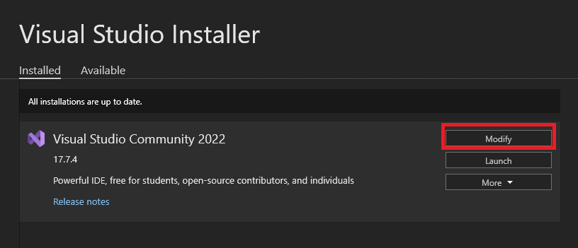
Search for the right version of your Visual Studio installation an click the „modify“ button on the right side. You will then be able to modify your existing Visual Studio IDE configuration.
4. Search for „class designer“
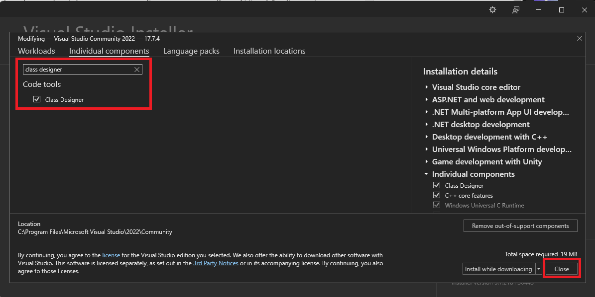
Inside of the „individual components“ tab, search for the „class designer“ component and mark it, so it will be a part of our changes. Confirm your selection with the button on the bottom right – this will trigger the change process for your VS installation. If it’s already installed you will only see a „close“ button.
Creating the UML diagram
If you have finished every previous step, you can now start with the actual process of creating your UML diagram automatically through Visual Studio.
Follow these steps:
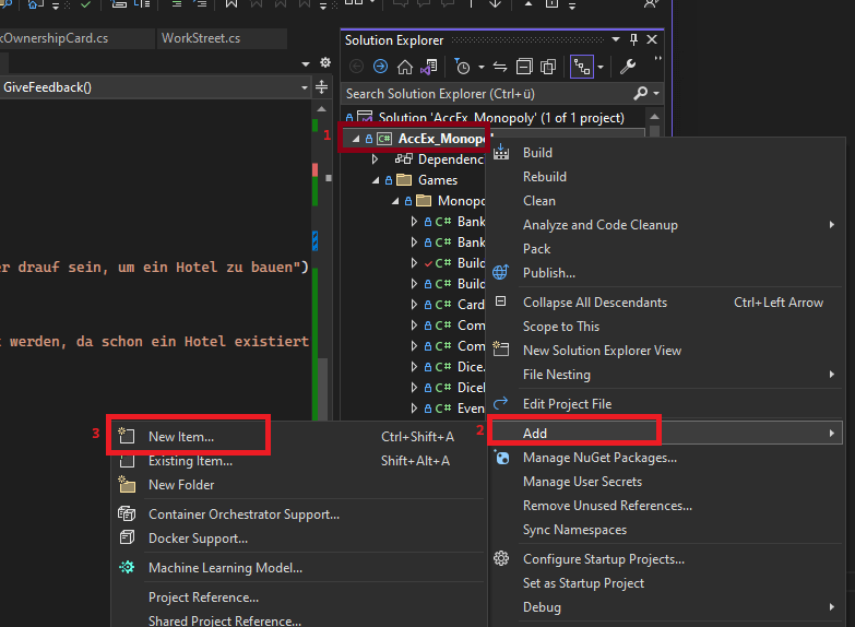
- Right click on your project (or a folder inside of it)
- Choose „Add“
- Select „New Item…“
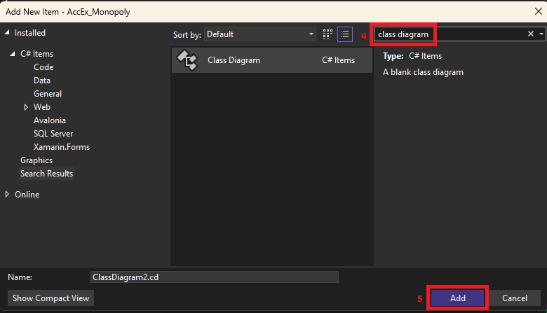
- Search for „Class Diagram“ and select it
- Confirm
Filling the diagram with life
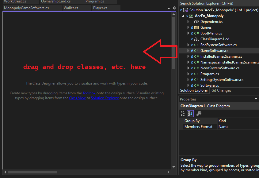
As you have created your class diagram now, it should look pretty empty, right? No problem! It’s not a bug, it’s an actual feature. You can decide which classes, etc. should actually be a part of this specific class diagram! Just play around by dragging and dropping some classes and interfaces on the class diagram „surface“ like in the image below:
The final result
In the last step you can take a look at my generated class diagram containing the class and the interface of the example from above. Please don’t get confused as I used an example project from my mentoring activity:
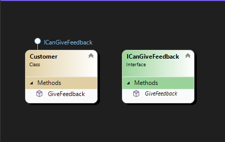
As you can see this is quite different from an actual UML diagram – but I think this is the closest you can get with Visual Studio without extensions.
More
See the following posts for more .NET related stuff:
